
Patching with Switch Matrices
by Chris Meyer of LearningModular.com
In many cases, a fully patched modular synth looks at best like an old-fashioned telephone switchboard … or at worst like a rat’s nest of cables. As a result, it’s nearly impossible to understand a patch with just a quick glance; each cable needs to be traced from its starting point to its destination, with cables often weaving in front of and behind each other. And along the way, those cables often obscure the controls on the individual modules.
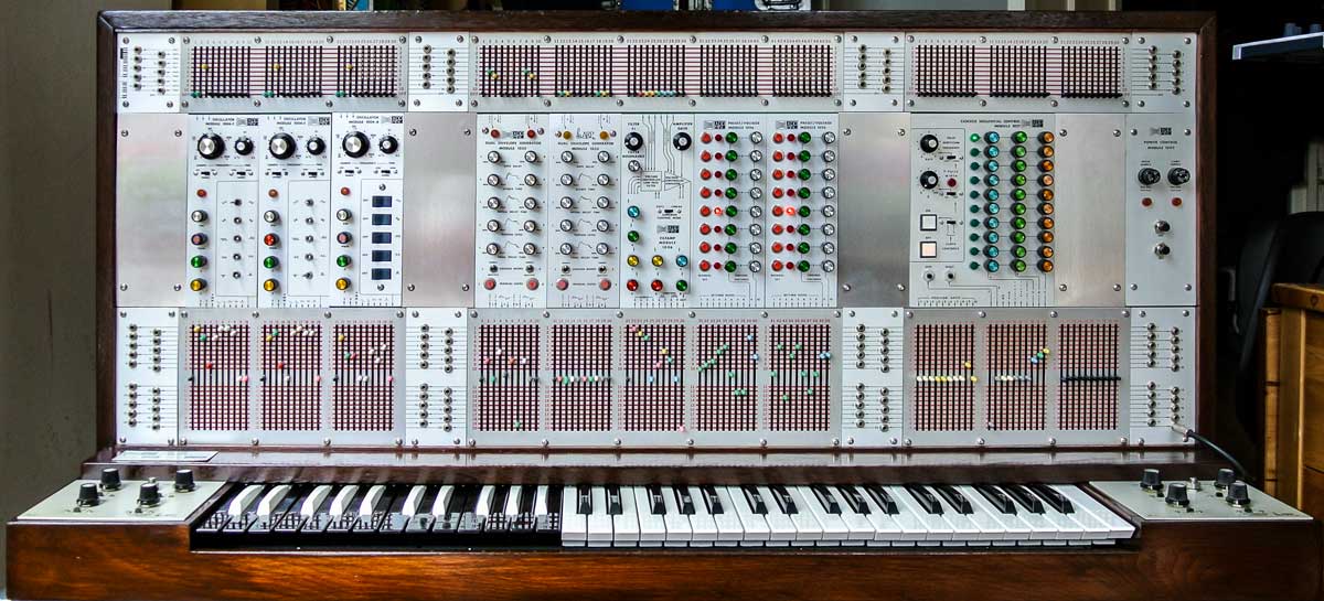
ARP co-founder David Friend once shared with me: “We looked at that and said, you know, there’s better ways to do this…” The better way ARP came up with for the 2500 was a set of switch matrices positioned above and below each module.
credit: Alex Ball
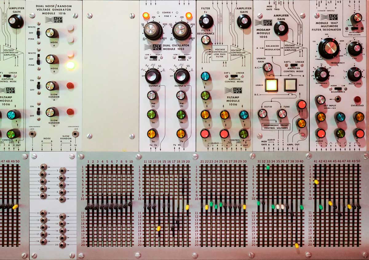
Each module is labeled to show which of its inputs and outputs are mapped to each vertical column of the switch matrices. The composer or performer then moved each color-coded switch vertically to decide which horizontal bus that input or output was connected to. Switches set to the same horizontal rows shared the signal on that bus between their associated modules.
credit: David Baron
As an ARP 2500 brochure of the time noted: “Matrix switch interconnection of the modules allows the panel areas to remain uncluttered and accessible no matter how complex the interconnection pattern…. Set up time is drastically reduced and quick visual checks of all signal and control voltage paths are possible.” This also made it much easier to notate and recreate a patch on the 2500.
Another advantage of the matrix switch system is that the player had access to essentially unlimited “multiples” with the ability to set as many modules inputs as they wanted to the same bus. The earliest models had 10 positions switches above the modules and 20 position switches below; later models features 20 positions both above and below. Although this was sufficient in most cases, a very complex patch could result in running out of horizontal bus lines available to make unique connections.
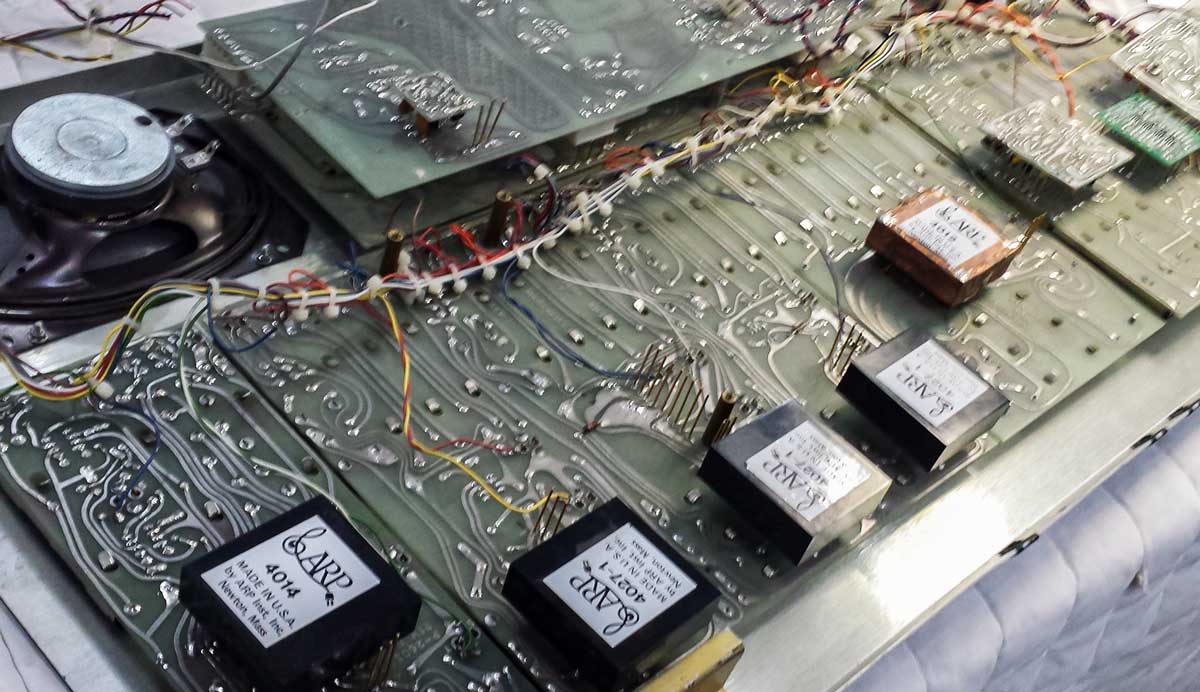
The biggest problem with this system was that the mechanical switches suffered from electrical crosstalk between adjacent busses, sometimes causing audio leakage and the occasional unexpected result. Alan Pearlman himself later conceded that their system was “a bit noisier” than the typical patch cable approach, and reverted to patch cables for the ARP 2600 – but with the addition of normalized connections pre-patched behind the front panel, creating a common default patch to save a musician time while setting up.
credits: Rob Currier/Retroaktiv
Most modular synthesizers today are still burdened by the use of traditional patch cables. However, there has been a minor movement to reintroduce matrix switches and even matrix mixers. The difference is that many of today’s modules feature a different hardware approach compared to the 2500. Whereas the switches in the 2500 carried the actual signals, modern matrix switch modules instruct other circuitry which connections to make, greatly reducing the chance for electrical crosstalk. Advanced matrix modules use computerized memory for instant recall of their routings, and in some cases allow voltage control over those connections. The front panel of the non-modular Arturia MatrixBrute is a good example. However, they all still point back to the switch matrices in the ARP 2500 as one of their ancestors.

